Connector Plating FAQs: Normal Force, Cycles, Temperature and more
Connector Plating: Normal Force, Cycles, Temperature, and other Essentials
Author: Danny Boesing @Samtec
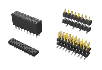
Plating affects the life and quality of the connector system, including corrosion resistance, conductivity, solderability, and of course, cost.
This is part two of a discussion with Phil Eckert, Samtec’s Quality Engineering Manager, and Matt Brown, Principal Engineer, about all things pertaining to connector plating. Here’s a link to part one. These blogs, and the upcoming ones in this series, answer connector plating questions that Samtec Quality and Processing experts are frequently asked.
Please note these questions deal primarily with gold and tin plating, as these are the most common connector plating options.
Should the normal force of the contact dictate which plating to use?
The short answer is yes. With tin plating, the general guideline is 100 grams of normal force per mated contact to achieve a gas-tight connection. Oxides can potentially build to the point where there are electrically resistive layers on the surface finish of tin. To make a good connection you need enough normal force to break through that oxide. When I say these connectors require 100 grams of normal force, we’re not talking about microminiature connectors. You typically don’t see tin plating on these small connectors because it’s difficult to generate the appropriate amount of normal force.
With gold, because it’s a noble metal and does not react with contaminants and pollutants in the atmosphere, you can go with less normal force, like 30-40 grams.
You might be familiar with the phrase “30 – 40 grams, end of life,” which refers to the amount of contact normal force after accounting for thermal fatigue. This would be the contact normal force after testing is completed, and after it’s been exposed to higher temperatures. Often, the contact beams relax, but you still want 30 – 40 grams (with gold plating). Please note this is a general guideline; I’ve seen EOEMs with miniature connectors with less than 30 grams that function well.
We mentioned before that gold plating requires 30 – 40 grams of contact normal force. We’re giving a range because the normal force required can be affected by the contact design. Namely, the more points of contact the better.
 What is the maximum continuous usage temperature of gold and tin plating?
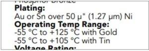
With tin plating, it’s 105° C, and gold is 125° C. BTW, many customers use the terms “maximum continuous usage temperature” and “Operating Temperature Range” synonymously.
There’s also peak temperature, which refers to a temperature that the device is exposed to that is above the operating temperature for a limited time. Reactions occur when you’re above the operating temperature — for example, corrosion or oxidation on the surface — and all reactions are accelerated by heat. A general rule of thumb is every 10° C rise in temperature doubles the reaction rate. Therefore, once you get to a certain temperature, reactions that were happening slowly, that would not affect connector life for years, are suddenly happening very quickly, and can cause your connector to fail rapidly.
You should be aware of the connector’s Current Carrying Capacity (CCC). Running current through a connector increases the temperature in and around that connector, so the 105° C and 125° C is a consideration with that given current level.
What is the typical thickness of these connector plating options?
With tin plating, Samtec recommends at least 100 µ” of tin plating on the solder tail, and in many cases, greater than 100 µ” in the contact area. Some specifications don’t have a top end for tin plating. Because tin is inexpensive, we recommend 100 µ” minimum.
For gold, 30 µ” is the standard for reliability. We talk with many customers who require 30 µ” of gold in their designs, but we know many more who use 10 µ” of gold, or even down to 3 µ” of gold (called “gold flash”). OEMs may specify 30 µ” of gold if the connectors are required to pass Mixed Flowing Gas (MFG) tests, where the unmated contacts are exposed to chemicals like chlorine, hydrogen sulfide, nitrogen dioxide, and sulfur dioxide. Connectors with 30 µ” of gold will pass this test, but 10 µ” will usually fail due to porosity.
 What are the maximum mating and unmating cycles of each connector plating?
This is a frequently asked, difficult question. Mary variables affect the number of cycles a connector system can handle. Of course, the first is the surface finish, and we know we’ll get more cycles out of gold. The base metal also plays a role, in that some base metals produce higher normal forces. A connector with very high normal forces can wear through the plating after many cycles.
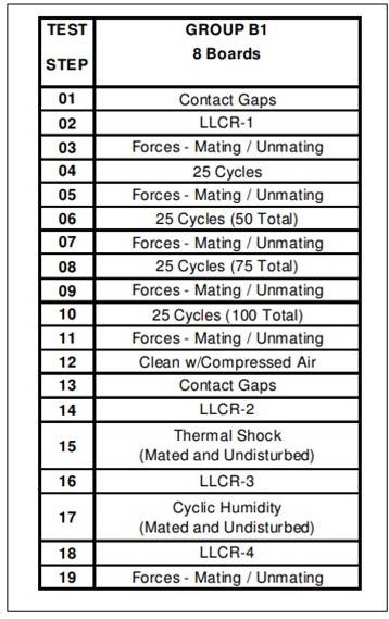
We test our 30 µ” gold connectors to 100 cycles. There’s no doubt many customers are getting more than 100 cycles out of their connectors, but these testing standards tests are repeatable and reflect real-world applications. To the right, you see a typical Samtec test plan, and the tests performed after cycling.
The most simple, practical advice we can give is, if you require more cycles use gold, and the more cycles, the more gold. Cycle counts are also impacted by environmental conditions like temperature, moisture, humidity, and what pollutants and contaminants (e.g., sulfur and chlorine) are in the atmosphere.
What are the advantages and disadvantages of Sn/Pb plating?
Tin/lead plating has been on its way out the door for the last 30 years, and still is! By most measures, tin/lead plating produces a superior solder joint. Tin/lead also mitigates whisker growth, especially for military and space applications. Dendritic whisker growth can form on a pure tin plate, possibly creating a short. There are plenty of documented cases of whiskers on pure tin causing catastrophic failures.
While there are popularly documented cases of tin whiskers causing catastrophic failures, the consensus is that matte tin is normally accepted provided the plating is of good quality with some thought that a Ni underplate used with matte tin further decreases the chances for whiskers.
Tin/lead plating also has a lower eutectic temperature, which can help protect sensitive components as they are processed. Tin/lead plating allows oven temperatures to be set at 15° C to 30° C lower compared to a pure tin finish. For example, a lead-free oven might be set to 245° C to 260° C; leaded applications may be set to 230° C, and are frequently lower.
The disadvantages of tin/lead are obviously the environmental concerns as represented in protocols like RoHS and REACH. Some customers might experience availability issues with tin/lead plated connectors, but that is uncommon.
The products in our Webshop