IDC or Crimp? May The Best Connector Win.
IDC or Crimp connector
Author: Danny Boesing @Samtec
IDC or Crimp? When discussing options for cable assemblies, designers frequently ask if we recommend discrete wire cable assemblies with crimped contacts or insulation displacement connectors (IDC) with ribbon cable. Our answer is it depends on your application. Crimped connectors and IDC are both reliable connector systems and each has its own list of advantages and disadvantages.
Before we get to those lists, just to make sure we’re all on the same page, here are quick definitions of each connector type, courtesy of Wikipedia:
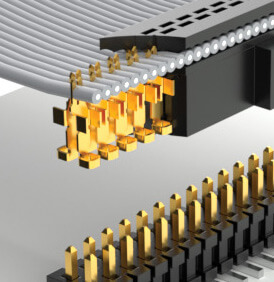 “An insulation-displacement contact (IDC), also known as insulation-piercing contact (IPC), is an electrical connector designed to be connected to the conductor(s) of an insulated cable by a connection process which forces a selectively sharpened blade or blades through the insulation, bypassing the need to strip the conductors of insulation before connecting.
When properly made, the connector blade cold-welds to the conductor, making a theoretically reliable gas-tight connection.”
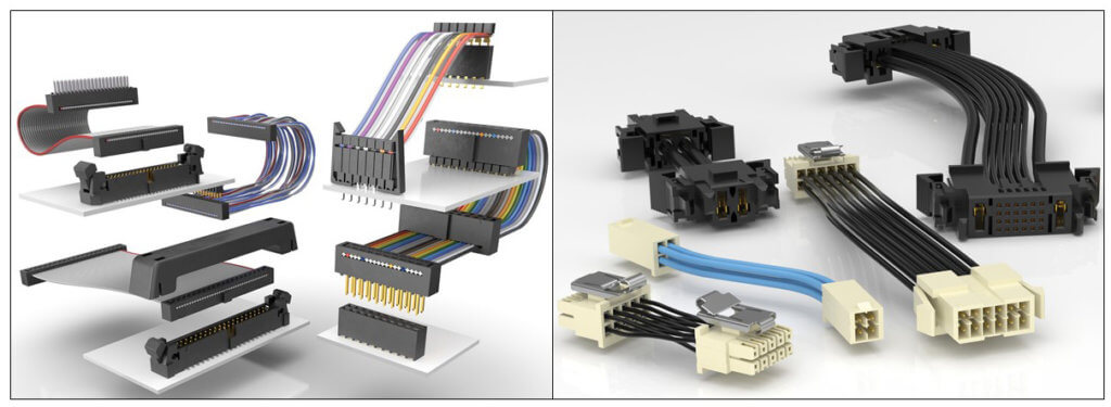
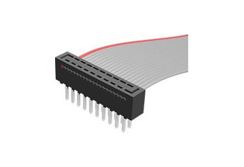
IDC cable assemblies are available on 1.27, 2.00, and 2.54mm pitch. Most are double-row connectors, but a few are single row.
 “Crimped connectors are a type of solderless connection, using mechanical friction and uniform deformation to secure a connector to a pre-stripped wire (usually stranded).
Crimping is used in splice connectors, crimped multipin plugs and sockets, and crimped coaxial connectors.
Crimping usually requires a specialised crimping tool …”
Discrete wire connectors come in a variety of centerlines, sizes, shapes, and wiring configurations.
Insulation Displacement Connectors (IDC)
IDC’s are quicker, and therefore less expensive, to manufacture. Literally dozens wires and contacts can be terminated at one time.
The insulation on the wires does not have to be stripped prior to termination, or soldered, or individually crimped. This saves a lot of time and therefore money.
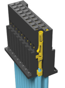
Most IDC’s can be terminated by a basic hand press or other simple tool. For that matter, generally, much lower forces are required to terminate the ribbon cable to the IDC contacts.
IDC has been around since the 1950’s and is an accepted connector design. It’s so accepted that connector companies offer a large variety of design and manufacturing options. They are available in a variety of wire gauges, pin sizes and centerlines. Mating connectors for the IDC cable assembly incorporate options to increase the ruggedness of the assembly with features like locking clips, ejection latches, strain relief, and polarization, to name just a few.
Assuming you are purchasing your components from a reputable connector supplier (like Samtec!), IDC’s are gas-tight and vibration-proof because of the quality of the design and manufacture of the contacts and plastic insulators which house them.
In the assembly process the metal blades penetrate any surface oxides on the wire.
In our opinion one of the biggest disadvantages of ribbon cable and IDC is the cable is relatively inflexible and stiff, and the cable pretty much has to travel from one point of termination to another in a relatively straight line, or with minimal bends and angles.
Crimped Connectors (Discrete Wire)
Because cable assemblies with crimped connectors almost always incorporate discrete (individual) wires and not ribbon cable, these crimp cable assemblies can fit into some tight areas that ribbon cable can’t. They can bend, angle, and flex into some tight bends and small nooks and crannies. As mentioned previously, IDC cable assemblies pretty much have to go straight ahead and can’t bend.
Discrete wire assemblies can break-out from a higher pin count connector to several smaller position connectors. You can also do this with IDC, but you have more flexibility and options with crimped connectors.
.jpg) Crimped systems allow designers to use two or more wire sizes in one cable assembly, allowing the same connector to route both signal and power. This design can save board space, and it can allow the designer to use fewer connectors. It is popular on 2.54 mm pitch connectors because those contact systems accept a wide range of wire gauges, from 20 to 30 AWG.
Crimped systems allow designers to use two or more wire sizes in one cable assembly, allowing the same connector to route both signal and power. This design can save board space, and it can allow the designer to use fewer connectors. It is popular on 2.54 mm pitch connectors because those contact systems accept a wide range of wire gauges, from 20 to 30 AWG.
Crimped connector assemblies let designers transition from one connector pitch to another. A common example is switching from 2.54 pitch to 2.00 mm pitch. Perhaps the most common application is a designer needs to connect their PCB to a PCB or device from another supplier. They may design a smaller pitch termination on their PCB to save real estate.
We frequently pull pins between — in other words, selectively populate — the plastic insulator to meet creepage and clearance requirements.
Like IDC, crimped contact systems are available in a large variety of design and manufacturing options: a variety of wire gauges, pin sizes, centerlines, latches, and options to increase the ruggedness of the system.
The biggest disadvantage is cost, primarily in assembly and manufacturing time, and tooling and assembly can be more complex.
I’m sure if I thought longer I would come up with more differences between these two systems, but I think we’ve covered the main points.
.
The products in our webshop
IDC & FFC flat
cable systems
.jpg)